日本語の記事はこちら
In this article, I'll construct a system with AWS Lambda to enable parallel image processing. The processing algorithm is based on Particle image velocimetry (PIV) which is one of the measurement technique utilized in the field of fluid mechanics.
Introduction
Before I started my job in Serverworks, I was a researcher in the field of fluid mechanics . In fluid mechanics, main target of study is flow of liquids, gases and collectively called fluids. Particle image velocimetry (PIV) is one of the measurement method which is utilized in this research field. High speed video cameras are used to record flows, and the flow is quantitatively measured by processing the recorded images. PIV is widely known in the field of fluid mechanics because of its advantage that can measure flow distribution in a wide space. One of the disadvantage of PIV is to require a long time to process images. This disadvantage is serious problem for researcher in case many images have to be processed. In this article, I'll try to process images in parallel to shorten the time required to the processing.
Definitions of terms
What is PIV?
PIV is a technology to measure fluid flows quantitatively by image processing. There are various methods of PIV with different image processing algorithms. In this article, I'll introduce Direct Cross-Correlation Method (DCCM), which is the most basic method in PIV. Image processing algorithms have to determine from where to where the fluid flows. In DCCM, cross correlation between parts of images is referred for the determination. To learn the detail of DCCM algorithm, please read technical books like this (in Japanese). Here, I'll summarize inputs and outputs of DCCM.
Inputs: Two image files, Input parameters (Grid size, Interrogation area and Search area, in numeric)
Outputs: Flow velocity distribution (Structured data) In the architecture suggested here, images are saved as BMP files. Input parameters and flow velocity distribution are saved as CSV file.
What is AWS Lambda?
AWS Lambda is a fully-managed service to run codes. The code is saved as a Lambda function, and trigger conditions can be set for it. The function is invoked when the trigger condition is met. Lambda is usually used to link services on AWS (ex.1, ex.2) or link external APIs and services on AWS (ex.1, ex.2). In this case, I'll use Lambda for image processing, and let it do hard calculation.
Why should PIV and Lambda be combined?
DCCM takes a long time to derive flow velocity distribution because it calculates cross-correlation many times. In such a case, it is an effective solution to use parallel computing with multiple CPU or multiple servers. The image processing in fluid mechanics generally performed with local environment on PC or on-premise servers. Thus the parallel computing requires an initial investment on servers or skill for parallel computing programming. The architecture that I explain here will show you the parallel computing without any initial costs using cloud computing. Lambda makes it easier to construct the environment compared with the architecture which consists of EC2 and SQS.
Detail of the architecture
Architecture for single processing
Before showing the architecture for parallel processing, I'll show you the single architecture which derive one flow velocity distribution from two images.
Figure 1 Architecture for single image processing A code of DCCM should be saved as a Lambda function "DccmOnLambda" in advance. An event source was set to invoke DccmOnLambda when a CSV file is saved on S3. By configuring like this, the image processing is executed as following:
- (1-1) Save two image files on S3
The event source of the Lambda function should be configured not to invoke at this time. - (1-2) Save the input CSV file on S3
- (1-3) DccmOnLambda is invoked.
DccmOnLambda reads two image files and the input CSV file to calculate a flow distribution. - (1-4) The flow distribution is written out as an output CSV file.
- (1-5) The output CSV file is save on S3.
The folder to save output CSV files is necessary to prevent the Lambda function from re-invocation.
This tutorial provides by AWS was helpful to construct this system. I recommend this to read.
Architecture for parallel processing
The architecture above is extended to enable parallel processing. The procedure of the parallel processing is shown in Figure 2.
Figure 2 Architecture for parallel image processing I created another Lambda function "csvdivide". It reads one CSV file, called parent-CSV, and create two or more CSV files, called child-CSV. The parallel image processing is performed along with the following procedure.
- (2-1) Save all image files on S3
- (2-2) Save parent-CSV on S3
- (2-3) Lambda function "csvdivide" is invoked by the parent-CSV.
- (2-4) Child-CSV files are generated.
- (2-5) Child-CSV files are saved on S3.
- (2-6) Each child-CSV files invoke Lambda function "DccmOnLambda".
- (2-7) Output CSV files are saved on S3.
How does it work?
I'll show you how the architecture works by processing actual images. I used PIV Standard Image, provided by Prof. Okamoto (Univ. Tokyo), as input images. I chose No. 01, 2D Wall shear flow/Reference, for the input of the test image processing. The four particle images are named from piv01_000001.bmp to piv01_000004.bmp. The particle images are shown in Figure 3 as GIF animation.
Figure 3 PIV Standard Image introduced to the test image processing
Single processing
At first, the single image processing was invoked to show how the Lambda function "DccmOnLambda" works. An input condition for the test processing is summarized below.
| Image size | 256 pixel x 256 pixel |
| Grid Size | 36 pixel |
| Interrogation Area | 33 pixel x 33 pixel |
| Search Area | 17 pixel x 17 pixel |
The input parameters are written on the CSV file as Figure 4 shows. Interrogation Area and Search Area are calculated as two times and plus one of the numbers on the CSV file because these should be odd numbers in DCCM.
Figure 4 Format of the input CSV The Lambda function "DccmOnLambda" is invoked when the CSV is saved on S3. Logs written by the Lambda function can be browsed with CloudWatch. The log in Figure 5 means the Lambda function is invoked properly, and the images are under processing.

Figure 5 Log of the Lambda function under single processing (under calculation)
The calculation was finished in two minutes. Figure 6 shows the log after the calculation was finished. According to the log, the billed duration was 112100ms for this computation. The log also shows only 28 MB of memory was used in the calculation. I set the memory as 1536 MB to allocate enough CPU for the Lambda function. Because CPUs are allocated proportionally to memories for Lambda functions, I could not reduce the memory. I observed it takes twice the time if memories, and thus CPUs, are reduced to half.

Figure 6 Log of the Lambda function under single processing (calculation completed)
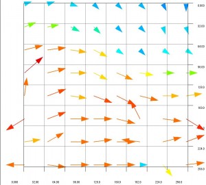
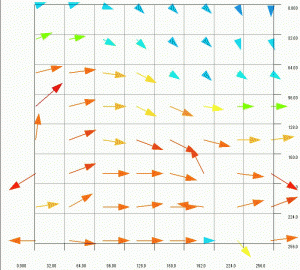
By opening the output CSV file with GraphR, flow velocity distribution is displayed as vectors like Figure 7. It seems the vectors describe the particle motion in Figure 3 well. We can also see some vectors point wrong direction. These vectors are called error vectors, and it is difficult to prevent them completely. It is possible to obtain more dense vector distribution by shortening grid size in the input parameter. Since maximum time out of Lambda function is five minutes, We have to be careful not to exceed it when calculating dense vectors.

Figure 7 Flow distribution derived by the image processing
Parallel processing
Now I'll try the parallel processing. A parent-CSV file like Figure 8 is saved on S3.

Figure 8 Format of parent-CSV
By saving the file, the Lambda function "csvdivide" is invoked. It reads the parent-CSV, and generates child-CSV files. In this case, three processes run in parallel: as we have four image files, flows between first and second, second and third, third and fourth images are calculated in parallel. Thus "csvdivide" saves three child-CSV files on S3. Figure 9 shows the log of "csvdivide".

Figure 9 Log of the Lambda function to divide CSV files
Each of the child-CSV files invokes the Lambda function "DccmOnLambda". In Log Group in CloudWatch, I can see three image processes which are running in parallel.

Figure 10 The log group which shows three image processes are running in parallel
Logs of each image process are shown as Figure 11. 12 and 13.

Figure 11 Log of image process A, one of the parallel image processes

Figure 12 Log of image process B, one of the parallel image processes

Figure 13 Log of image process C, one of the parallel image processes
The three velocity distributions are summarized as the GIF animation in Figure 14. Generally speaking, it takes a lot of work and time to obtain flow velocity distributions. In this article, I succeeded in constructing the system to derive multiple flow distributions in parallel by just uploading files. In cases the flow varies over time, it is important to obtain a lot of flow distributions in short time. The parallel image processing will be useful to analyze unsteady flows.

Figure 14 Flow distributions obtained by the parallel image processing (Click the image to see the animation)
Summary
I constructed the system to run image processes in parallel with AWS Lambda. The system is simple enough that I, experience AWS less than one year, can design and construct it. The upper limit of time out of Lambda function, five minutes, will be a bottleneck when velocity distributions with high resolution are required. This is also the case with processing large images.
If you are interested in, please contact us, or send an e-mail to ![]()
- Takahisa Shiratori, Dept. Tech. 2


